Many people think the design of oscillators is black magic as such circuits usually either work or not. Especially beginners are glad when they finally get a circuit to oscillate and attributes such as signal quality are usually secondary and often neglected. This article is going to show two easy tricks that can be implemented in almost any oscillator design.
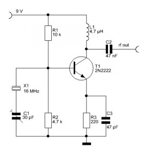
The following picture shows a standard oscillator circuit for fundamental mode crystals.
To be precise, the oscillator is a Miller crystal oscillator. In case you are wondering where the LC tank circuit in the collector path of T1 is, look closer! The inductor L1 has an unavoidable capacitance known as ‘parasitic capacitance’ or ‘stray capacitance’. I personally prefer the term parasitic capacitance because the term stresses that the capacitance is a (usually) unwanted phenomena. Parasitic capacitance is the reason why inductors have a self-resonance frequency (SRF) mentioned in their datasheet.
How can we improve the standard Miller oscillator in regards of phase noise and spectral purity?
The first step is to improve the power supply. Usually circuits in the amateur radio community use some sort of linear voltage regulator to stabilize the supply voltage to a fixed voltage. Linear voltage regulators have the unfortunate habit of introducing a significant amount of noise into the system. [1] It should be apparent that a high noise floor in the supply voltage has a direct influence on the output signal of an oscillator. The noise directly modulates the oscillator circuit and produces plenty of phase noise. Luckily, there’s an easy remedy for this problem; a low pass filter.
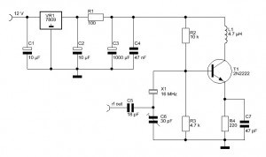
A simple RC low pass filter, consisting of R1 and C3, on the output of the linear voltage regulator improves the supply voltage noise drastically. C4 is a block capacitor and is supposed to short out all kinds of short spikes in the supply voltage.
Just this tiny add-on is cheap and can be implemented by anyone. If you discipline yourself to always include a low pass filter after a linear voltage regulator you will see great improvement in the overall noise figure of your circuit. A block capacitor in the supply voltage path in front of any significant part of a circuit, such as an ICs or transistors, should be considered mandatory also.
The second improvement I implemented is the RF output. Instead of taking the RF output from the collector of T1, the circuit uses a capacitive voltage divider, consisting of C5 and C6. Ideally, the reactance of C5 is chosen as small as possible in regards to C6. Since any capacitive or inductive load on the output will slightly detune the crystals frequency, a buffer amplifier is absolutely necessary before applying the RF to any other circuitry.
Ideally such a buffer amplifier will have its own low pass filter from the linear voltage regulator output and a blocking capacitor.
It goes without saying that there should be another low pass filter on the output of the RF buffer amplifier to suppress harmonics of the RF signal effectively.
Links and Sources:
[1] Analog Applications Journal (2005): John C. Teel. Understanding noise in linear regulators. Texas Instruments Incorporated. http://www.ti.com/lit/an/slyt201/slyt201.pdf
Westerhold, S. (2012), "Low Noise Oscillator Design". Baltic Lab High Frequency Projects Blog. ISSN (Online): 2751-8140., https://baltic-lab.com/2012/08/low-noise-oscillator-design/, (accessed: April 25, 2024).
Funding:
If you liked this content, please consider contributing. Any help is greatly appreciated.


hi,
it’s nice article
i ask how Change in resistor & caps values in this Miller crystal oscillator for make it Operate efficiently for (each bands Especially 20m band).
or i can use design for wide range like this : COLPITTS 1 To 20 MHz Crystal Oscillator
http://www.electronicecircuits.com/electronic-circuits/colpitts-1-to-20-mhz-crystal-oscillator
The oscillator design I posted should work over a wide frequency range. It will be perfect for the 20m band. If you decide to use the Colpitts oscillator from the web-page you linked, just make sure you apply very clean power. I wrote in this article how this can be accomplished. Good luck with your project! What are you planning on building?
ok then iuse your design . i see when i search also some designs interesting for beginners like me.
http://www.youtube.com/watch?v=VMoIAIC5sOU
I planning to build 20m ssb radio for one fixed band why ?
because
1-i need to study whats Differences, Filters,…etc.
so hope this will be Works efficiently compared to commercial radio.
2-should i build by use Materials available here & i hope your Write articles about how measure filter / home made …etc
using easy Materials available in any places
thx you so much
It is interesting, thanks for sharing.
Actually my field of work is not related to rf, but I need to use an oscillator for one of my designs.
I want to know is it possible to use QCM as the crystal in this oscillator, and it’s a 5 MHz crystal.
Also I want to know as I want to know the changes in frequency of the crystal due to environmental changes, should I get the output from the crystal leads or some other nodes in circuit, for example to reduce the reading noise.