The concept I will outline in this article is absolutely nothing new. Back in the days, engineers and hobbyists would use analog noise sources in combination with a spectrum analyzer to determine the frequency response of a filter. The concept is very simple: the wide-band noise source is connected to the input of the filter and the output of the filter is connected to the input of the spectrum analyzer. As long as the noise level is somewhat flat over a wide frequency range, one can read the frequency response directly on the spectrum analyzer. So the question is, does this work with a cheap DDS signal generator and a scope with FFT spectrum display, as well?
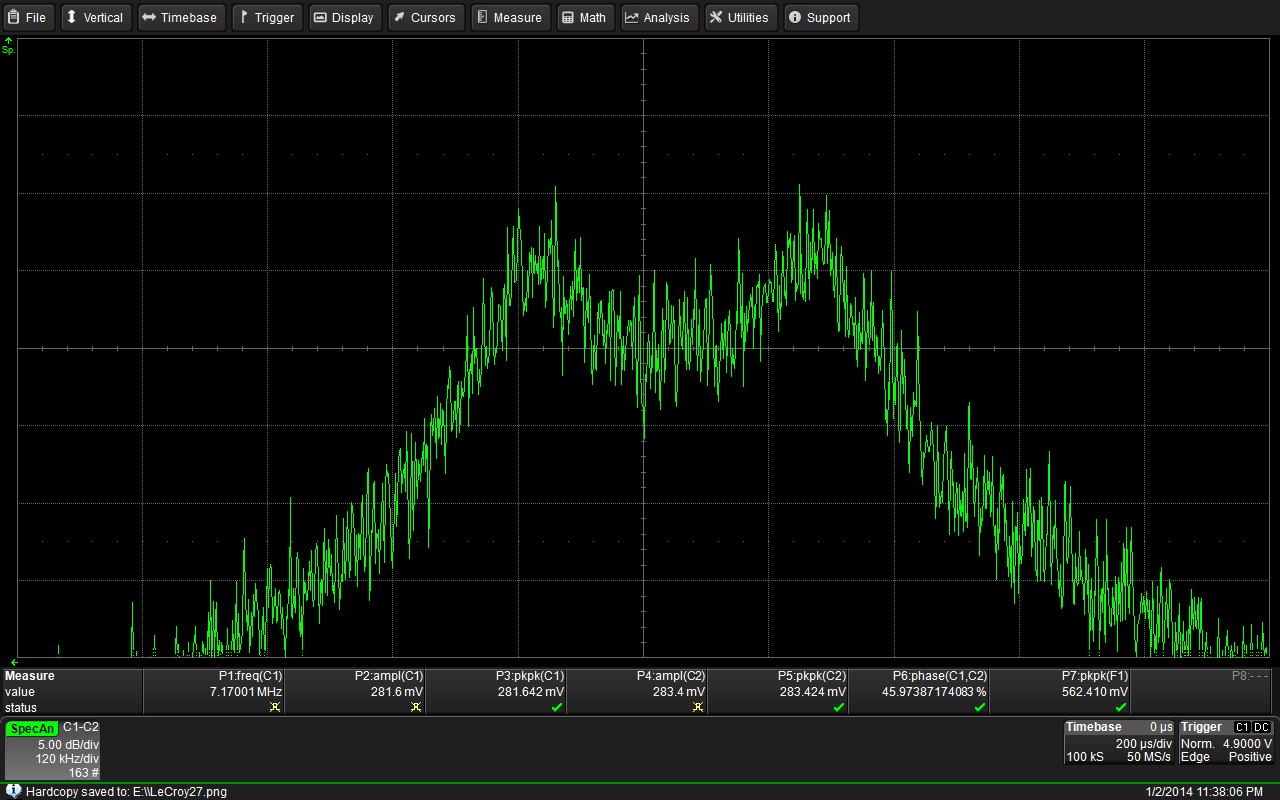
I used a Rigol DG1022 signal generator as noise source. The generator has a “noise” option. The first thing I wanted to know is how linear the output spectrum of this noise generator is. I captured the spectrum with a Teledyne LeCroy HDO4024. The frequency range shown is 1 MHz to 80 MHz.

Output spectrum of the DG1022’s noise function
Looks like it’s pretty usable ’til about 10 MHz. If you need more bandwidth, you either need a better dig gen or you could build a simple analog noise source using a reverse biased Zener diode and a couple of transistor amplifiers. For very high frequencies and high linearity, there are special noise diodes available, as well. But for HF and HF experiments, a Zener diode and a few 2N2222 as amplifiers are more than enough.
The first filter I tested is a bandpass filter for the 40m amateur radio band. Since the filter was designed for a 50 Ohm impedance, care needs to be taken to set the scope and the signal generator to 50 Ohms, as well. The FFT spectrum view of the oscilloscope was set to “Max Hold.” After a few seconds of noise input, this is what I got:
Frequency response of a 40m-Band filter
But how accurate is the result? Let’s compare.
The following image shows a 10.7 MHz ceramic IF filter measured using the noise setup as described before.

10.7 MHz ceramic IF filter measured using a noise source
As you can see, the filter curve is not very smooth, but the general filter parameters are clearly visible. In order to compare the measurements, I used a classic sweep generator setup. The generator swept between 9.7 MHz and 11.7 MHz over a time span of 10 seconds. I picked 10 seconds so that I could simply use the Max Hold function of the oscilloscope’s spectrum analyzer without having to bother about synchronization. The following picture does not only show the results, but it also shows the exact setting I used to set-up the FFT spectrum analysis.
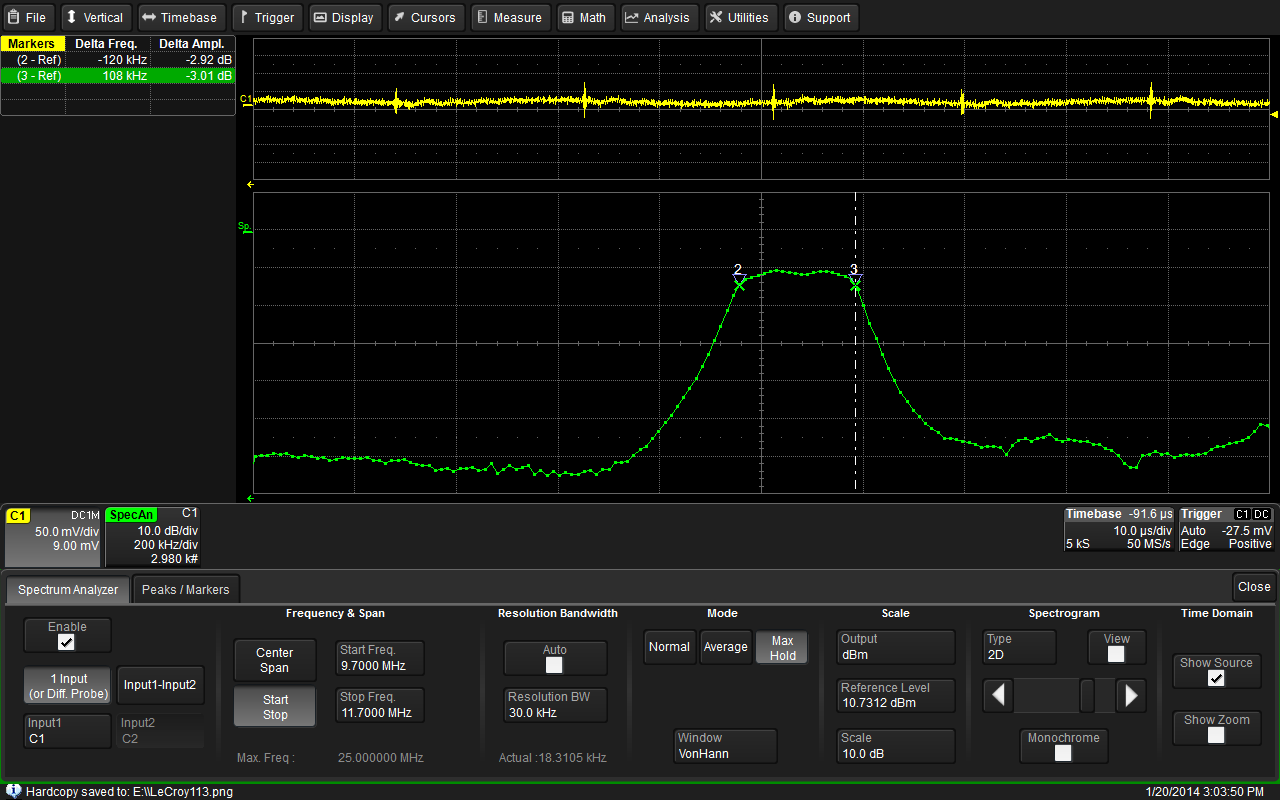
10.7 MHz ceramic IF filter measured using a sweep generator
The comparison shows that this method words very well to use a modern oscilloscope with FFT spectrum analysis to determine the characteristics of a filter’s behavior in the frequency domain.
Westerhold, S. (2014), "Measuring filter response using a noise source". Baltic Lab High Frequency Projects Blog. ISSN (Online): 2751-8140., https://baltic-lab.com/2014/01/measuring-filter-response-using-a-noise-source/, (accessed: April 16, 2024).
Funding:
If you liked this content, please consider contributing. Any help is greatly appreciated.
Great article and nice technique.
Nice post, for those of us without a stand alone ($) generator capable of noise generation. Maybe you can build and test a stand alone HF noise generator from simple parts. Lots of examples on the Web. But I’d like to see your recommendations and results. 73’s David
Yes sir, if I can put this into my time schedule, I will absolutely do that. Way before I could afford fancy generators and expensive Network Analyzers, all I worked with was a simple oscilloscope with a homebrew spectrum analyzer add on and a nice noise source with an actual noise diode for the GHz range. Like I always say, electronics doesn’t require cash, it just requires the skill to do everything within your budget.